
Initialize the control endpoint
In the last chapter, the USB controller of the AT90USB1287 was successfully configured as a USB device. Now we need endpoints so the microcontroller can act as a USB device.
Every USB-capable device requires at least one endpoint, the so-called control endpoint. This endpoint is the only endpoint that can be configured as an IN and OUT endpoint at the same time and is used to control and initialize the USB device.
The AT90USB1287 has a total of 832 bytes of memory (DPRAM) that can be used for a total of seven USB endpoints. This memory is divided as follows:
Max. 64 Bytes for endpoint 0 (Default control endpoint)
Max. 256 Bytes for one endpoint (split up in 1/2 banks)
Max. 64 Bytes for the other endpoints (split up in in 1/2 banks)
Before the endpoints can be used, they must be configured. Each configuration or memory reservation of an endpoint must be done in ascending order. So endpoint 0 must be created first, followed by endpoint 1, endpoint 2, etc.
If the microcontroller is connected to the USB, the USB host (i.e. the PC) triggers a USB reset. The USB reset disables all endpoints (with the exception of endpoint 0) and must be reconfigured. Therefore, the USB reset should serve as an entry point for the configuration of the control endpoint by the software. The end of the USB reset can be detected using the EORSTI bit in the UDINT register. This additional interrupt must be activated during initialization:
// Previous
USBCON |= (0x01 << VBUSTE);
// Add
UDIEN |= (0x01 << EORSTE);
And update the ISR:
ISR(USB_GEN_vect)
{
	...
	if(UDINT & (0x01 << EORSTI))
	{
		UDINT &= ~(0x01 << EORSTI);
		_USBDeviceState = USB_STATE_RESET;
		Endpoint_Configure(0, ENDPOINT_TYPE_CONTROL, ENDPOINT_CONTROL_SIZE, 0);
	}
As soon as the USB reset has been completed, the corresponding interrupt flag is deleted and the status of the USB driver is updated. The endpoint 0 is then configured. The address of the endpoint, the type of the endpoint, the size of the endpoint and the number of memory banks are transferred for the function call. Since a low-speed USB device is to be implemented in this example, the size of the transmission and thus the size of the endpoint is fixed at 8 bytes.
An endpoint is always configured according to the following scheme:

The CPU can only access one endpoint at a time. The active endpoint is determined via the UENUM register and only values from 0 to 7 can be written into this register. The endpoint is then activated via the EPEN bit in the UECONX register. Now the configuration bits for the direction and the endpoint type can be set in the UECFG0X register, as well as the endpoint size and the number of memory banks in the UECFG1X register. Finally, the ALLOC bit is set in the UECFG1X register, whereby the required memory is reserved for the endpoint. If everything went well, the CFGOK bit in the UESTA0X register is set and the endpoint is ready for use.
The CFGOK bit is not set if there is not enough DPRAM available to reserve the requested memory!
When implementing the endpoint actication flow, it must also be taken into account that the endpoints can only be configured in ascending order. The functionality of the memory reservation is described in chapter 22.7 of the data sheet:

When reserving memory for an endpoint, the USB controller automatically searches for unused memory. As soon as he finds one, the endpoint directly above it is pushed up if necessary. The memory area of all other endpoints is not moved, which can result in two endpoints using the same memory area!
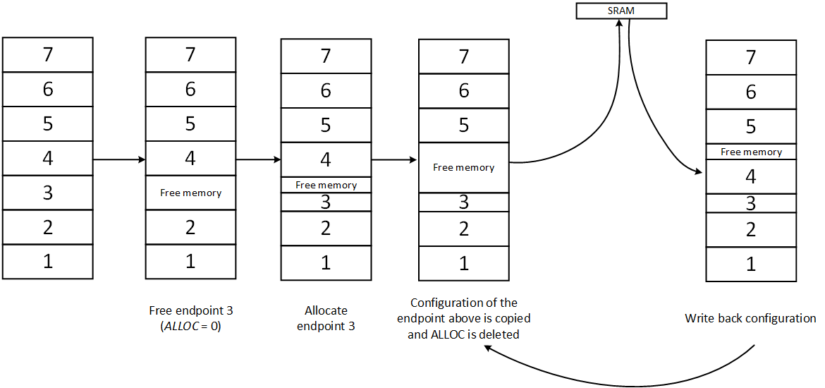
By avoiding gaps in the memory and avoiding an incorrect configuration (see picture), it must be ensured that the memory of all endpoints that have a higher address than the configured endpoint slides down, so that memory gaps in the DPRAM are avoided , Since the USB controller only carries out this process automatically for the endpoint with the address k + 1, all other endpoints must be moved manually by the software. To do this, the endpoints are selected and deactivated in order. Then it must be checked whether the ALLOC bit is set.
ALLOC set: Memory is allocated and must be moved
ALLOC cleared: Memory is free and can be overwritten with the data of the overlying endpoint
To move an endpoint downwards, the configuration data of the respective endpoint is saved and the ALLOC bit is cleared, which frees up the memory used. Then the configuration data of the endpoint are written back and the ALLOC bit is set, whereby the memory is reserved again.
This procedure must now be implemented as a code.
The following code section converts the given size of the endpoint (in bytes) into the corresponding bit mask. This bit mask is shifted to the correct position and copied into the corresponding register. Finally, the configured endpoint is activated and can therefore be used.
As a check, the result of the configuration can be output using a red or green LED.
Last updated